GeeKee CeeBee

Welcome to GeeKee CeeBee's Page: House of Mechatronics Projects & Lessons.
Contact Email: Ceebee1108@gmail.com
Follow me on Youtube
__________________________________________________________________________________________________________________________________

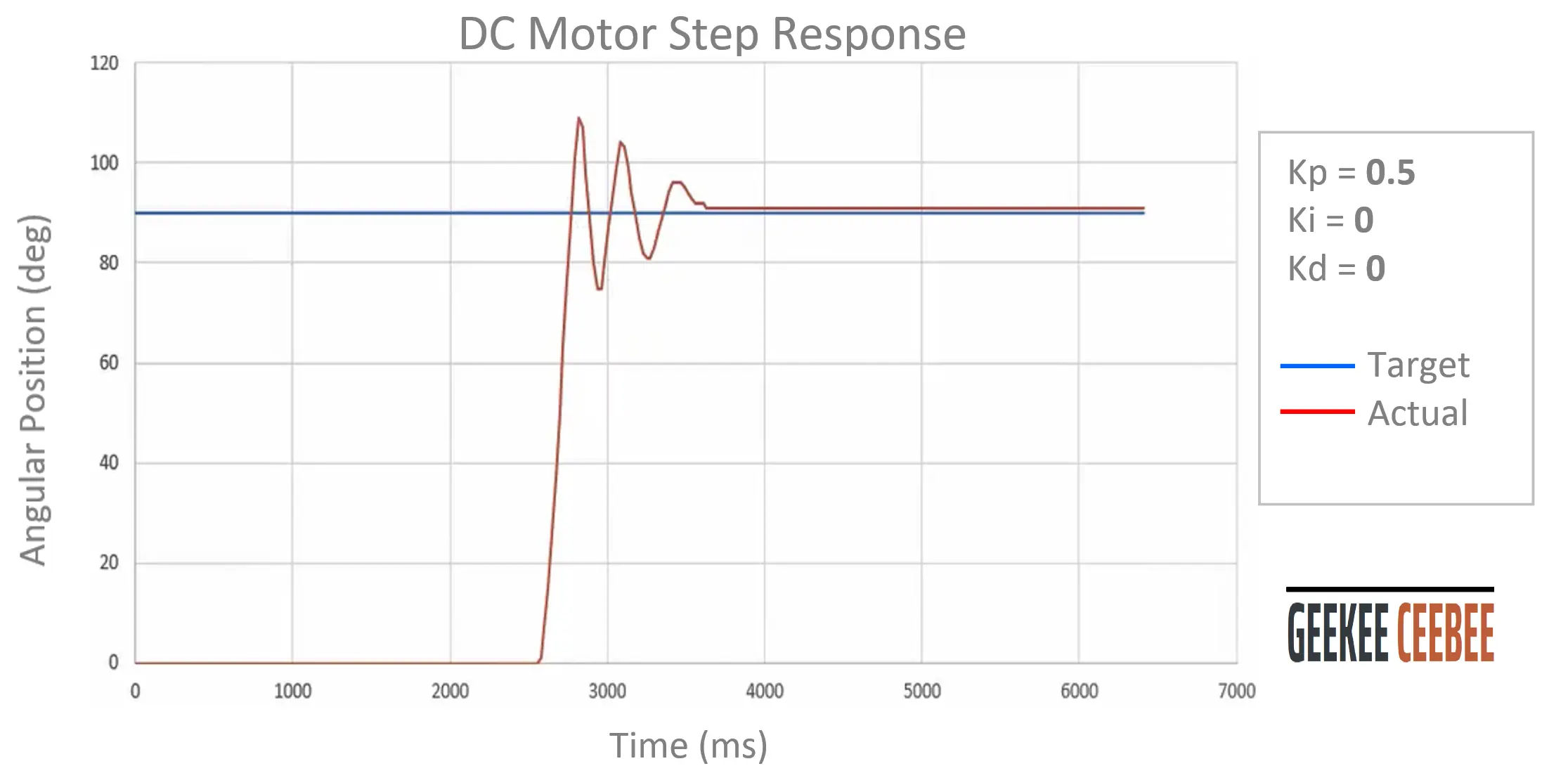
PID TUNING, STEP RESPONSE, DC MOTOR

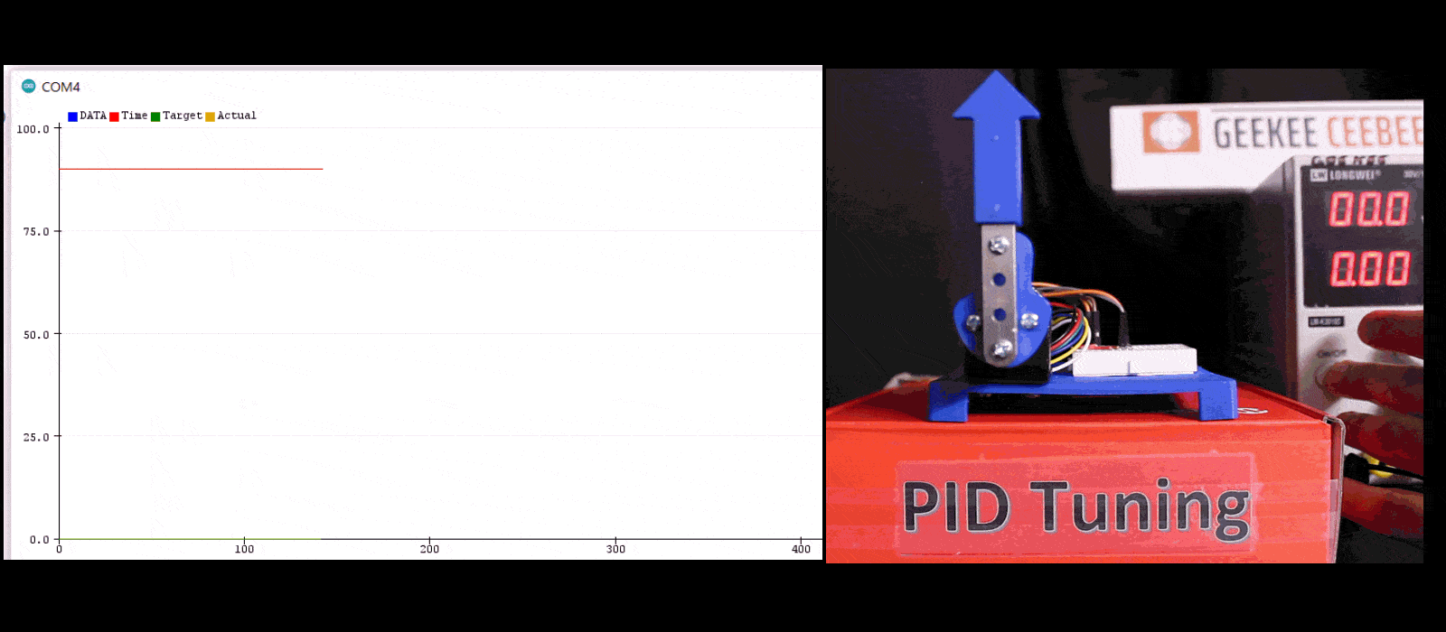
Step by step practical example of tuning PID controller of a DC motor using Arduino.
Use physical example of tuning PID gains
Physical system includes a DC motor with optical encoder for position feedback
Tune for motor's step response to achieve target position

Components List

Arduino Uno (Affiliate Link)
DC Motor Double-ended Shaft (BestTong 775)
L298N Dual H-bridge Motor Driver (Affiliate Link)
DC Power Supply (6-12V)(Affiliate Link)
Jumper Wires and Breadboard (Affiliate Link)

Demonstration video

In this video guide, you will learn how to tune PID gains for a DC motor step response. The motor is controlled with an arduino using PWM voltage control. Plots and live motor behavior are shown under different PID gains. Please watch the whole video for better understanding.


Steps

Let’s start proportional gain. Try Kp =1 and we can see the motor overshoots the target position and continues to oscillate. Need to tune Kp gain first.

Let’s reduce the Kp term to Kp=0.5. We see less oscillations after the motor overshoots the target. We are on the right path. Next step is to further reduce Kp gain.

Next plot is with Kp=0.25. We have reduced the number of oscillations, but the motor is still overshooting the target position. At this point we can further reduce Kp gain or add Kd term to incorporate some damping in the system response to reduce the overshoot.

Next plot is with some added Kd gain, Kd = 10. And, we have dampened the system a little bit but not enough. As we can still observe overshoot.

Next plot is with Kd=50. We can clearly see that the system response has now become overdamped. As the motor never reaches the target position. We need to reduce the Kd gain to get system to critically damped state.

Next plot is with Kd= 30, and we can see we are very close to the target position. However, system response is still slightly over-damped. So, let’s reduce Kd term even more.

Next plot is with Kd=24. And now we can see this system is now tuned. There’s no overshoot or steady state error. Our system is now stable

Additionally, we never used Ki gain for tuning PID controller for this system. That’s because our system does not have steady state error. We can simply add Ki term to see how this will make our system unstable. Let’s try Ki=0.1 just for fun.

Ki gain makes our system unstable. Therefore, Ki is not needed for this application. However, if you have a system that's showing steady state error you would follow the same approach. After tuning Kp and Kd gains, one can simply tune Ki gain to minimize steady state error. Hope this was helpful and thank you for stopping by.

__________________________________________________________________________________________________________________________________